Language:
 ∷
∷

∷
 ∷
∷
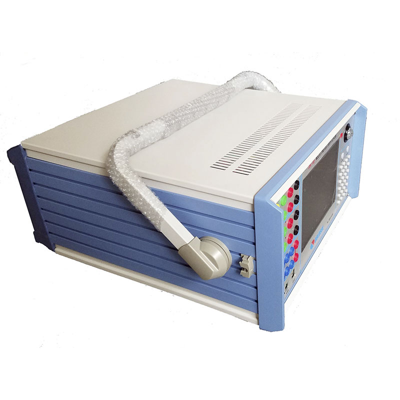
Home > Secondary Current Injection Tester
Advantage
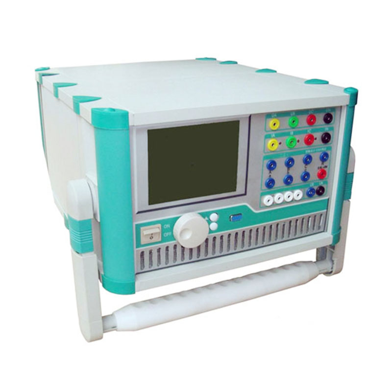
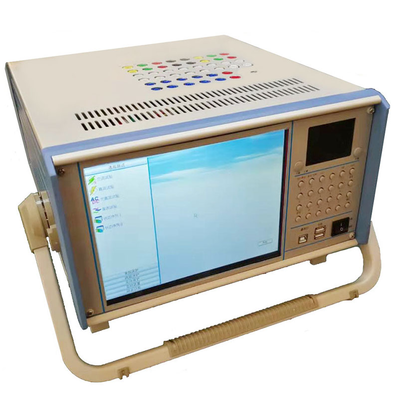
1.High-Performance Industrial Control Computer
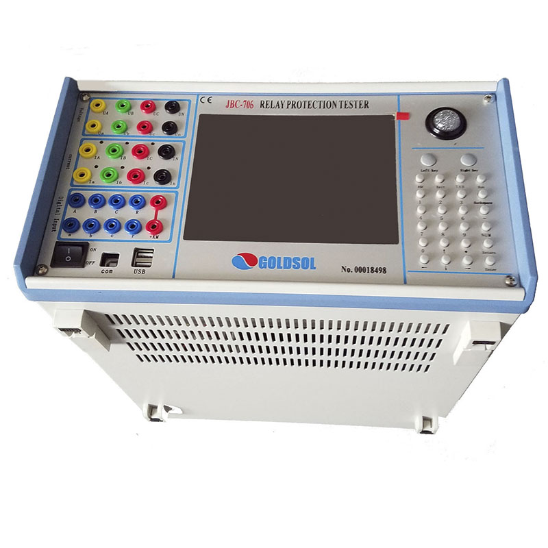
-High performance Industrial control computer is adopted as the controlling computer, through which you can run the windows operating system directly. 8.4"LVDS true color LCD display, tracking ball and optimized keyboard are allocated on the faceplate of this tester, which can be used without the external mouse and keyboard. USB interface, 10-100M net mouth and serial communication interface are located on the back plate of this tester, through which you can access data, communicate data and upgrade software conveniently.
-The whole process and the result of the test will all be showed on the LCD. The English operational interface of the complete set is very friendly and convenient. The tracking ball and keyboard on the faceplate will implement the operation. The operation is simple and convenient, and is easy to be mastered. Operator only needs a little knowledge of computer.
-Keyboard and mouse interface are also allocated on the faceplate. If you would like to use the external mouse and keyboard, through pluging them with corresponding interfaces, you can operate this tester just like operate a desk-top computer.
2.Digital Signal Processor Microcomputer
-High-speed digital controlling processor is adopted as the output core of the tester. 32 bit double precision arithmetic is employed in the software, through which arbitrary high-accuracy waveforms of each phase can be produced. Since integrative structure is adopted,the structure of the tester is layed compactly.The distance of data transmission is short with tight structure, which overcome the problem of fewer points of waveform output due to long data communicational line and narrow frequency band when using the test controller controlled directly by PC.
3.D/A Conversion and Low-Pass Filtering
-High precision D/A converter is employed for ensuring the precision and linearity of current and voltage in the whole range.
-Due to high density of fitting ponit, fidelity of waveform is high and harmonic component is small, which don’t have a strict requirement on the low-pass filter. Consequently, it has good characteristics of transient, phase frequency and amplitude frequency, which is easy to perform accurate phase-shifting and harmonic superposition and ensures very high precision even when the frequency is high.
4.Voltage and Current Amplifier
-For phase current and voltage, we persist in adopting high performance linear amplifier output mode in order to make the current and voltage source to directly output all kinds of waveforms from the DC waveform to the waveforms including all kinds of frequency components, such as square wave, combined waveform overlapped by each order harmonic, fault transient waveform, etc. In addition, the output waveform is clear and smooth without high-frequency radiated interference with neighboring equipments. It can simulate well all kinds of current and voltage characteristics under the circumstance of short circuit fault.
-For power amplifier circuit, we adopt import power parts with high-power and hi-fi module style as power output, combining with heat dissipation structure layed elaborately and reasonably, it has enough large power redundancy and thermal capacity. The power amplifier circuit has overheat, overflow, overvoltage and short circuit protections. When overflow occurs in the current circuit and overload or short circuit occurs in the voltage circuit, it will limit the output power automatically, switch off the whole power amplifier circuit and give alarm signal.In order to prevent the overheat of the power amplifier for long time operating under large current, a software time terminating system under large current is set in this tester. It can work for a long period when outputting is 10A or below. When the current is over 10A, the tester will start up the software time termination order. When time is up, the software will forbid power output automatically and give alarm signal. The higher output current is, the shorter the limiting time will be.
5. Digital Input and output
-This tester has 8 channels digital input and 4 channels output, please refer to the corresponding instruction to hardware structure of 702 “ Tester.
-The switching input circuit is compatible for both the empty contacts and 0-250V electric potential contacts in the input and output circuit. When the electric potential contacts are selected, 0-6V belongs to closed switch and 11-250V belongs to open switch. The switching capacity can test the action time and the action time interval of every phase switch’s contact conveniently.
-The part of the digital input is isolated from the resources of the mainframe and the amplifier. The end of the digital input is hung, so the common end of the digital input is separated from the Common End UN, IN of current and voltage parts.
-Switching potential input has directivity, you should connect the common end with the positive terminal of potential, and connecting the input end with negative terminal of potential for ensuring the potential of common end is higher than the one of input end. In practice, you should connect the input common end with +KM, and connecting the negative terminal of contact with input end.
-The output part is the idle contact output of relay. Output capacity is DC:220V/0.2A,AC:220V/0.5A. Output of switching capacity is independent of voltage, current, input and all other parts. Action process of each digital output part is different in each testing module.
6. Auxiliary DC Power Supply Output for Special Use
-A circuit of special adjustable DC power supply output is allocated on the rear panel, which has 110V and 220V two shifts that can be used as test standby power supply on the spot. We still set a potentiometer for this power supply, it can be adjusted within the range of 80%-110%. Rated current of this power supply is 1.5A, which can be used as DC power supply of protective tester or switch loop supply. If overload or short circuit occurs, corresponding protector tube will be burned out (2A/250V), you will only need to change this protector tube at that time.
Technical Parameters
Current generators General
Setting range Accuracy <0.2%typical
6-phase ac(L-N) 6*0…30A Distortion ≤ 0. 5%typical
3-phase ac(L-N) 3*0…60A Resolution 4.0mV
1-phase ac(L-N) 1*0…180A Generator, general
6-phase dc(L-N) 6*0…10A Frequency range
3-phase dc(L-N) 3*0…20A Sine signal DC…1000Hz
1-phase dc(L-N) 1*0…60A Transient signal DC…3000Hz
Power Frequency accuracy 0.01%
6-phase ac 6*260VA/W Frequency resolution 0.01Hz
3-phase ac 3*400VA/W Phase angle range -360…+360
1-phase ac 1*1080VA/W Phase angle accuracy 0.1
6-phase dc 6*180VA/W Digital Input and Output
3-phase dc 3*320VA/W Digital input
1-phase dc 1*780VA/W Number 8
General Input characteristic:10-250VDC or free contact
Accuracy <0.2% typical Time resolution 1m s
Distortion ≤ 0.5%guaranteed Max.measuring time 9999s
Resolution 1mA Digital output
Voltage Generators Type Free relay contact
Setting rang Number 4
6-phase ac(L-N) 6*0…120V Break capacity ac 0.5A,250V
6-phase ac(L-L) 0…240V Break capacity dc 0.5A,60Vdc
6-phase dc(L-N) 6*0…160V General
6-phase dc(L-L) 0…320V Nominal supply voltage 240Vac
Power Permissible supply voltage220-264Vac
6-phase ac(L-N) 6*70VA Nominal frequency 50/60Hz
6-phase ac(L-L) 3*140VA Permissible frequency 45-65Hz
6-phase dc(L-N) 6*80W Operating temperature -5…+50℃
6-phase dc(L-L) 3*160W Miscellaneous
PC-Connection USB
Ground Socket 4mm banana socket
Measurement items
1. Relay test
|
Relay type |
Test item |
Test module |
Note |
|
Signal relay |
Relative test item |
AC test Intermediate relay DC test |
If the relay with AC/DC input, please choose “AC/DC test”. For the signal relay with small rated current, please choose voltage loop test of the device. |
|
Time relay |
|||
|
Intermediate relay |
|||
|
Reclosing relay |
|||
|
Current relay |
Relative test item |
AC test Current voltage extremely inverse current relay DC test |
Test sequence component relay at sequence component module of “AC test”. Test the extremely inverse current relay at “extremely inverse current”. |
|
Over (less) voltage relay |
|||
|
Sequence component relay |
|||
|
Synchronism-check(or phase comparison)relay |
|||
|
Extremely inverse current relay |
|||
|
Differential relay |
DC magnetic properties |
Differential relay Differential test Harmonic test |
Please wire correctly according the method of “differential test”. |
|
Harmonic brake characteristics |
|||
|
Proportional brake characteristics |
Differential test Differential relay AC test |
||
|
Power ( direction ) Relay |
Relative test item |
Power direction AC test |
Please choose wiring method and protect the approximate action boundary before test. |
|
Impedance relay |
|||
|
Synchronous relay |
Relative test item |
Synchronous test AC test |
During the test, UA as the system side and UB as test side at “synchronous test” module, can test operating frequency, operating voltage, operating phase, and automatically make pene- contemporaneous test. |
|
Frequency relay |
Relative test item |
Frequency test |
Can test Operating frequency and Slip closed lock value. |
2. Microprocessor-based protection device
|
Types of relay protection |
Test item |
Test module |
Note |
|
|
Line protection |
Multi-stage over-current |
Relative test item |
AC Test Frequency Test Power direction |
Can do most of the relay and micro computer test at “AC test” module. |
|
Over (less ) voltage |
||||
|
Sequence components voltage and current |
||||
|
Frequency devices |
||||
|
Power directional protection |
||||
|
Reclosing and conversion failure |
Relative test item |
Group test State series |
Required synchronous and no voltage test, Ua as shunt side voltage output |
|
|
Distance and zero sequence |
Distance and zero sequence set value calibration |
Stepped impedance Zero-sequence protection |
“Stepped impedance” and “zero sequence protection” can one-time automatic test multi-stage , various fault types , distance and zero sequence value of various phase |
|
|
Impedance characteristics |
Impedance phase characteristics |
|||
|
Power frequency variation distance |
Set value calibration |
Power frequency variation distance |
The fault current should be set enough, for example 10~15A. |
|
|
Composite voltage Locking (direction)current |
Over-current, low voltage, negative sequence voltage,latching over-current. |
AC test |
Some of the “low voltage” and “negative sequence voltage” injected by different terminal, you should change it during the test. |
|
|
Low cycle, low voltage load shedding device |
Relative test item |
Synchronous low cycle Frequency Test AC Test |
If other conditions meet the requirements, the device did not operate, check if the device need input current and switch contacts. |
|
|
Generator transformer protection |
Differential protection |
Proportional braking characteristics |
Differential relay Differential protection AC test |
Generator differential protection, “differential protection” when tested, it can be regarded as the wiring Y / Y, high and low voltage side balance coefficients (=1) are a transformer protection. The " differential test " focus on curve characteristics search, includes Proportion of braking border search , proportion of braking designated test, harmonic brake border search and harmonic restraint sentinel test , comprehensive test differential protection . |
|
Harmonic brake characteristics |
Differential test Differential protection Harmonic test |
|||
|
Field loss protection |
Relative test item |
AC test |
Please note the angle between output current and voltage. |
|
|
Excitation protection |
||||
|
Composite voltage locking ( direction) over-current (Reserve) |
Relative test item |
AC test |
|
|
|
Others |
Automatic synchronizing device |
Relative test item |
Synchronous test |
Wiring correctly according the instruction manual. |
|
Protection device |
Action logic and action time for each switch |
State series |
Wiring correctly is important. |
|
|
Bus bar differential protection Fiber-optic lines differential protection |
Relative test item |
AC test |
Please refer to Annex 6 for the description of BP 2B and RCS - 915 in the southern part protection. Before the test, make sure that the device forms a “self-loop”, if yes, the protection action value should be equal to half the setting value. |
|
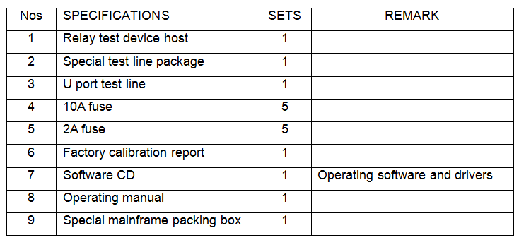
Accessaries
Contact: Mr.Luo
Phone: 86 13071289809
Tel: 86-27-82423362
Email: goldsol@foxmail.com
Add: No.128, Sanyang Road,Hankou Wuhan